Understanding the Connex Platform
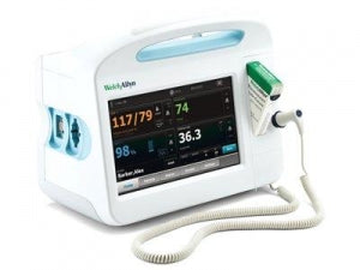
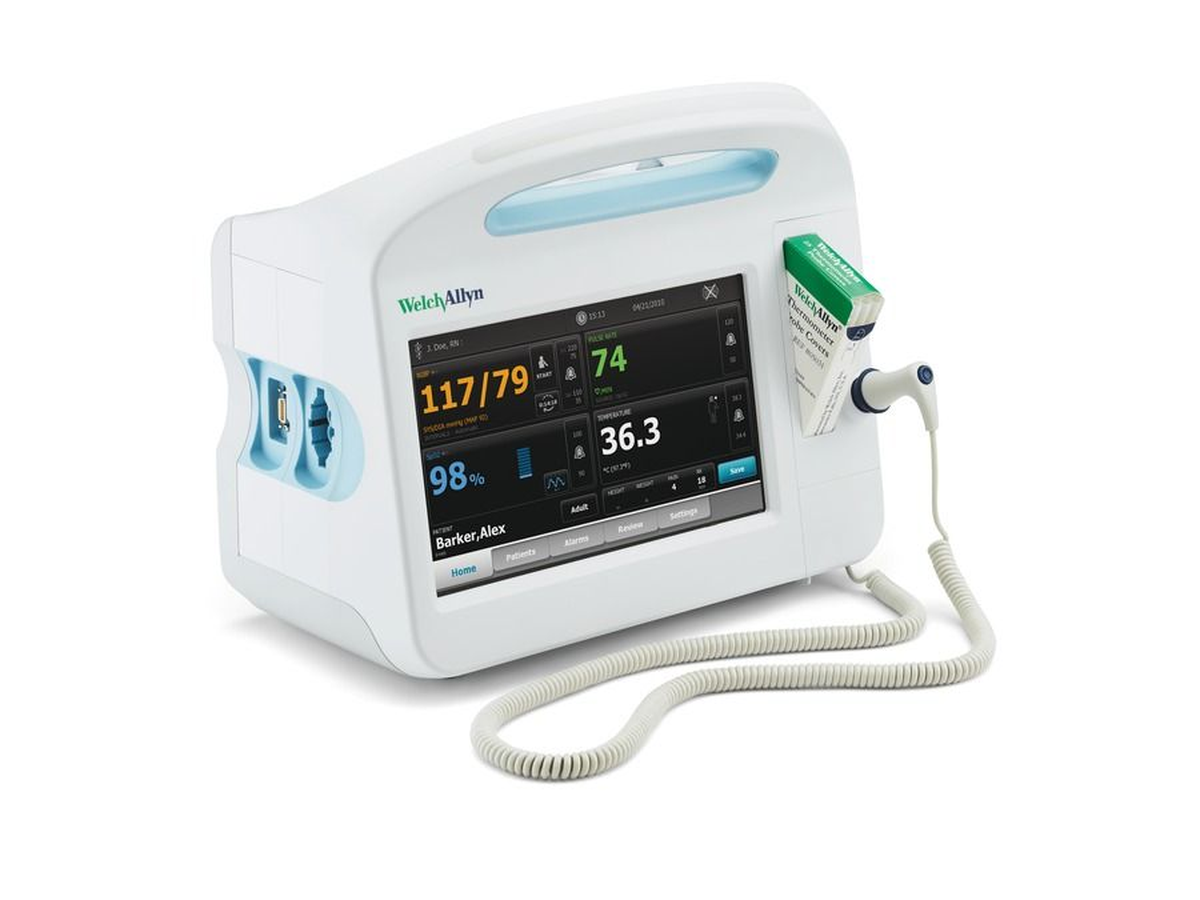
The Welch Allyn Connex Vital Signs Monitor represents a significant advancement in patient monitoring technology, integrating multiple physiological measurements into a single, network-connected platform. Available in several configurations (Connex 6000, 6300, 6500, and 6700 series), these devices are designed for use in hospitals, clinics, and ambulatory care settings where accurate, rapid vital signs assessment is critical.
The Connex platform architecture consists of several integrated subsystems: the main processing unit with touchscreen interface, measurement modules (NIBP, SpO2, temperature), communication interfaces (WiFi, Ethernet), and power management systems. Understanding the interaction between these subsystems is essential for effective troubleshooting and repair.
System Architecture Overview
Hardware Components
The Connex monitor integrates several key hardware modules:
- Main Processing Board: ARM-based processor running embedded Linux, responsible for measurement coordination, user interface, and network communications
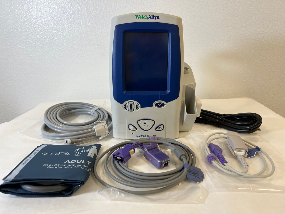
- NIBP Module: Oscillometric blood pressure measurement system featuring SureBP® technology for rapid readings in 15 seconds
- SpO2 Module: Available with either Masimo SET® or Nellcor® pulse oximetry technology, providing continuous oxygen saturation monitoring
- Temperature Module: Compatible with SureTemp® Plus thermometers and Braun ThermoScan® tympanic thermometers
- Optional Modules: Capnography (EtCO2), 3/5/12-lead ECG, and respiration rate monitoring
Software Architecture
The Connex operating system is a specialized embedded Linux distribution with proprietary measurement algorithms and communication protocols. The system supports bidirectional communication with electronic medical record (EMR) systems via HL7 messaging protocols, enabling automated documentation of vital signs.
Common Problem: Blood Pressure Measurement Failures
Symptoms
- "Unable to determine blood pressure" error messages
- Measurements timing out before completion
- Consistently elevated or reduced readings compared to manual auscultation
- Excessive measurement times (>60 seconds)
Root Cause Analysis
NIBP failures in the Connex platform typically stem from pneumatic system issues, sensor calibration problems, or cuff selection errors. The SureBP algorithm is particularly sensitive to proper cuff sizing—incorrect cuff size is responsible for approximately 40% of measurement failures in clinical environments.
Diagnostic Procedures
- Cuff System Verification: Inspect the FlexiPort cuff connection for proper seating. The Connex uses a one-handed connection system that should audibly click when properly engaged. Test cuff integrity by manually inflating to 200 mmHg and observing pressure decay—acceptable leak rate is <5 mmHg per minute.
- Pneumatic System Test: Access the biomedical service mode by pressing and holding the "Menu" and "Power" buttons simultaneously for 10 seconds. Navigate to "NIBP Diagnostics" and select "Pneumatic Test." The system will run automated leak detection, valve function tests, and pump performance verification. Document all results.
- Calibration Verification: Using a certified blood pressure simulator (FlukeBiomedical ProSim 8 or equivalent), verify measurement accuracy at three standard pressures: 80/50, 120/80, and 200/100 mmHg. The Connex should measure within ±3 mmHg for systolic and ±2 mmHg for diastolic pressures.
- Algorithm Performance Test: Test SureBP algorithm function using the simulator's motion artifact mode. The Connex should successfully complete measurements with simulated patient movement—failure indicates algorithm processing issues requiring software update or hardware replacement.
Resolution Procedures
Cuff Replacement: Replace defective cuffs with genuine Welch Allyn FlexiPort cuffs. Verify correct cuff size selection: Small Adult (18-26 cm), Adult (23-33 cm), Large Adult (31-40 cm), or Thigh (38-50 cm). Document cuff size recommendations on the device for clinical staff reference.
Valve Assembly Replacement: If pneumatic testing reveals valve malfunction, replacement requires partial disassembly. Remove the rear housing (four Phillips screws), disconnect pneumatic tubing (note routing for reassembly), and replace the valve block assembly (Part #: NIBP-VALVE-001). After replacement, run complete pneumatic diagnostics and calibration verification.
Software Updates: Algorithm improvements and bug fixes are periodically released via firmware updates. Connect the Connex to the facility network and navigate to Settings > About > Software Update. Follow the on-screen prompts to download and install updates. Note: Do not interrupt power during software updates as this may corrupt the system.
Common Problem: SpO2 Measurement Issues
Symptoms
- "No Pulse" or "Check Sensor" messages
- Erratic or fluctuating oxygen saturation readings
- Inconsistent pulse rate detection
- SpO2 values significantly different from arterial blood gas results
Root Cause Analysis
SpO2 issues typically relate to sensor problems (damaged LEDs or photodetectors), poor probe placement, patient-related factors (peripheral vasoconstriction, motion artifact, nail polish), or module calibration errors. The Connex supports both Masimo and Nellcor sensors—correct sensor type must be configured in system settings.
Diagnostic Procedures
- Sensor Verification: Using a finger pulse oximeter simulator (FlukeBiomedical Index 2 or equivalent), test sensor function independent of patient factors. The simulator provides known SpO2 and pulse rate values—compare device readings to simulator settings. Acceptable variance is ±2% for SpO2 and ±3 beats per minute for pulse rate.
- Cable and Connection Inspection: Examine the SpO2 cable for kinks, breaks, or connector damage. Test cable continuity using a multimeter. Replace damaged cables immediately as intermittent connections cause erratic readings.
- Module Configuration Check: Verify SpO2 module type matches installed sensors. Navigate to Settings > Configuration > SpO2 Module and confirm correct selection (Masimo SET or Nellcor). Incorrect configuration causes "Sensor Not Recognized" errors.
- Ambient Light Interference Test: Excessive ambient light (particularly surgical lighting or infrared heat lamps) can interfere with optical sensors. Test in normal room lighting versus high-intensity lighting to identify environmental factors.
Resolution Procedures
Sensor Replacement: Replace defective sensors with manufacturer-approved alternatives. Masimo sensors: M-LNCS (reusable) or M-LNCS Adtx (adhesive). Nellcor sensors: DS-100A (disposable) or OxiMax MAX-A (reusable). Document sensor type and lot number for quality tracking.
Module Replacement: If simulator testing confirms module failure, replacement requires accessing internal components. Power down the system, disconnect all cables, and remove the rear housing. The SpO2 module is located on the right side of the main board (viewed from rear). Disconnect the ribbon cable, remove two securing screws, and lift module straight up. Install replacement module, ensuring proper seating, and reconnect ribbon cable. Perform complete functional testing before returning to service.
Common Problem: Network Connectivity Issues
Symptoms
- Unable to connect to WiFi or Ethernet network
- Intermittent network disconnections
- EMR data not transmitting automatically
- "Communication Error" messages
Root Cause Analysis
Network issues in the Connex platform typically stem from configuration errors, network infrastructure problems, firewall restrictions, or hardware failures. The Connex requires specific network configurations including static IP addresses or DHCP reservations, proper DNS settings, and firewall exceptions for HL7 messaging.
Diagnostic Procedures
- Network Configuration Verification: Access network settings via Settings > Configuration > Network. Verify correct IP address, subnet mask, default gateway, and DNS servers. These should match facility IT specifications.
- Connectivity Testing: Use built-in network diagnostic tools to test connectivity. Navigate to Settings > Diagnostics > Network Test. The system will attempt to ping the default gateway, DNS servers, and configured EMR interfaces. Document results for each test.
- Signal Strength Assessment (WiFi): For wireless configurations, verify signal strength of at least -60 dBm. Weaker signals cause intermittent connectivity. Position the device within direct line-of-sight of access points when possible.
- Port and Protocol Verification: Confirm the EMR interface is configured for the correct protocol (HL7 2.x typically uses port 2575). Verify firewall rules allow bidirectional communication on required ports. Work with facility IT to verify network configuration.
Resolution Procedures
Network Reconfiguration: If configuration errors are identified, correct settings per facility IT specifications. For facilities using dynamic IP assignment, recommend configuring DHCP reservations based on device MAC addresses to ensure consistent network identity.
WiFi Module Replacement: If hardware failure is suspected, the WiFi module can be replaced. Access the internal components by removing the rear housing. The WiFi module is located on the left side of the main board (viewed from rear). Disconnect the antenna cables (note positions for reassembly), remove mounting screws, and lift module. Install replacement, reconnect antennas, and verify operation.
Preventive Maintenance Protocol
Daily Checks (Clinical Staff)
- Visual inspection for physical damage
- Verify all cables and sensors are properly connected
- Clean touchscreen and device surfaces with approved disinfectant
- Check battery status if using mobile configuration
Monthly Checks (Biomedical Engineering)
- Performance verification using simulator equipment
- Network connectivity verification
- Software version documentation
- Physical inspection of cuffs, cables, and accessories
Quarterly Checks
- Complete calibration verification (NIBP, SpO2, temperature)
- Deep cleaning of all modules and accessories
- Battery conditioning cycle (for mobile units)
- Documentation review and maintenance log update
Annual Checks
- Comprehensive electrical safety testing per IEC 60601-1
- Complete functional verification of all modules
- Firmware updates to latest stable version
- Replacement of consumables (cuffs, sensors) per manufacturer recommendations
- Documentation of device history and service records
Technical Specifications Reference
| Parameter | Specification |
|---|---|
| Blood Pressure Range | Systolic: 40-270 mmHg, Diastolic: 10-245 mmHg |
| Blood Pressure Accuracy | ±3 mmHg (per ISO 81060-2:2013) |
| SureBP Measurement Time | 15 seconds (typical), 45 seconds (maximum) |
| SpO2 Range | 0-100% (accuracy ±2% from 70-100%) |
| Pulse Rate Range | 25-240 beats per minute (accuracy ±3 bpm) |
| Temperature Range | 86°F to 113°F (30°C to 45°C) |
| Temperature Accuracy | ±0.2°F (±0.1°C) |
| Display Type | 8.4" color touchscreen, 800x600 resolution |
| Network Connectivity | WiFi 802.11 a/b/g/n, Ethernet 10/100 Mbps |
| Power Requirements | 100-240VAC, 50-60Hz, or internal rechargeable battery |
| Battery Life (Mobile Units) | 4-6 hours continuous operation, 8-10 hours standby |
| Operating Temperature | 50°F to 95°F (10°C to 35°C) |
| Storage Temperature | -4°F to 140°F (-20°C to 60°C) |
Frequently Asked Questions
⚠ Critical Safety Information
Electrical Safety
- Perform electrical safety testing after any repair involving internal components
- Verify proper grounding on all AC-powered configurations
- Test leakage current per IEC 60601-1 standards
- Document all safety testing results in device service records
Clinical Safety
- Never return a device to clinical use without complete calibration verification
- Apply calibration labels with dates and technician identification
- Ensure all accessories (cuffs, sensors, cables) are within manufacturer expiration dates
- Train clinical staff on proper device operation and limitations
Data Security
- Connex monitors may contain patient health information (PHI)
- Follow HIPAA-compliant procedures when decommissioning or repairing devices
- Ensure secure disposal of storage media if replacing internal components
- Maintain audit logs of all access to device configuration and data
Legal Disclaimer: This guide is intended for qualified biomedical equipment technicians with appropriate training. Always consult the manufacturer's service manual and follow institutional policies. Unauthorized repairs may void warranty and compromise patient safety.