Understanding PanOptic Optical Technology
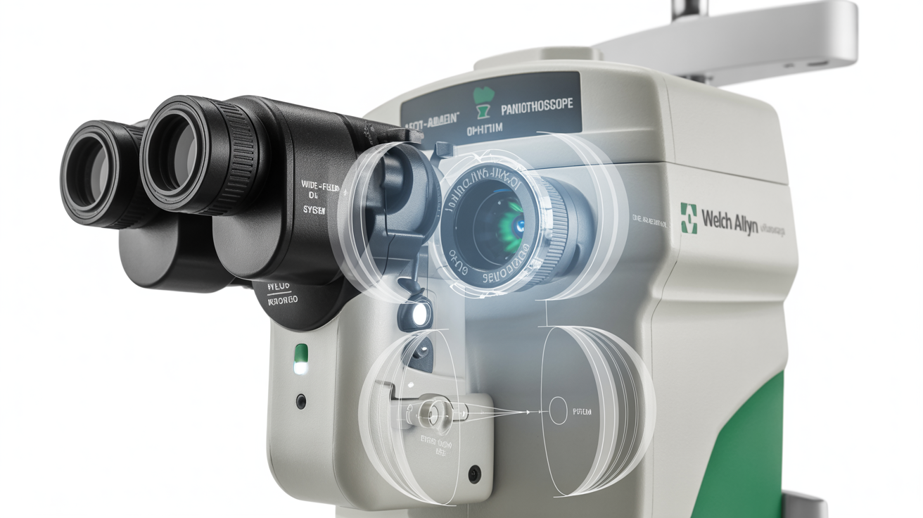
The Welch Allyn PanOptic Plus Ophthalmoscope represents a revolutionary departure from traditional ophthalmoscope design, utilizing a patented optical system that provides a 5x larger view of the fundus compared to standard ophthalmoscopes. This expanded field of view (25 degrees versus 5 degrees in conventional models) enables clinicians to visualize up to 95% of the optic disc in a single view, dramatically improving diagnostic capability.
For biomedical technicians, understanding the unique optical architecture of the PanOptic is essential for effective troubleshooting and maintenance. Unlike conventional ophthalmoscopes that use a simple focusing lens system, the PanOptic incorporates a complex multi-element optical assembly with proprietary coating technologies and precise alignment requirements.
Optical System Architecture
Light Path and Illumination System
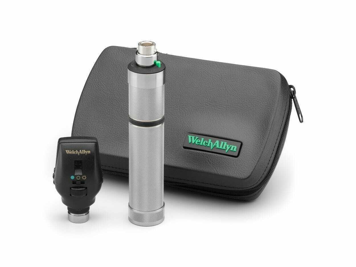
The PanOptic utilizes a Halogen HPX® illumination system generating 3.5V of optical power. The light path originates from the lamp assembly, passes through a condensing lens system, reflects off a primary mirror assembly, and projects through the optical head to the patient's eye. This design provides consistent, shadow-free illumination across the enlarged field of view.
Critical to optical performance is the precise alignment of the primary mirror and condensing lens system. Any misalignment—typically resulting from impact damage or improper reassembly—will manifest as uneven illumination, dark crescents in the visual field, or complete loss of image quality.
Corneal Viewing Lens System
The PanOptic incorporates a proprietary corneal viewing lens that can be engaged by rotating the aperture selector. This lens is specifically designed to work with the PanOptic's unique optical geometry and cannot be successfully substituted with generic replacement lenses. The viewing lens assembly includes anti-reflective coatings that minimize internal reflections and maximize light transmission.
Common Problem: Dim or Uneven Illumination
Symptoms
- Reduced brightness compared to known good units
- Bright center with dim periphery (vignetting)
- Dark crescents or shadows in visual field
- Flickering or intermittent illumination
Root Cause Analysis
Illumination issues in the PanOptic typically stem from lamp degradation, optical misalignment, or contamination of optical surfaces. The Halogen HPX lamp has a rated life of approximately 150 hours but may degrade faster in high-use environments or if subjected to mechanical shock.
Diagnostic Procedures
- Lamp Assessment: Remove the PanOptic head from the handle and inspect the lamp through the bottom aperture. Signs of lamp failure include darkened glass envelope, broken filament, or visible deposits on the inner glass surface. Compare brightness to a new lamp using a light meter—acceptable brightness is >90% of new lamp output.
- Handle Voltage Test: Using a multimeter, verify the handle provides 3.5V ±0.2V to the lamp contacts. Lower voltage indicates handle battery depletion or internal resistance issues. Higher voltage suggests handle regulator failure and will dramatically shorten lamp life.
- Optical Alignment Inspection: With a new, known-good lamp installed, project the light onto a white surface at 30 cm distance. The illuminated area should be uniformly bright with no dark spots, crescents, or uneven patches. Any irregularity indicates optical misalignment requiring optical bench realignment.
- Optical Surface Cleaning: Inspect all accessible optical surfaces (corneal viewing lens, rear lens assembly, mirror) for contamination. Use compressed air to remove loose particles, then clean with lens cleaning solution and lens tissue. Never use alcohol or aggressive solvents on coated optics as this will damage anti-reflective coatings.
Resolution Procedures
Lamp Replacement: Remove the PanOptic head by rotating the collar counterclockwise. Insert the lamp removal tool (supplied with unit) into the lamp access holes and rotate counterclockwise to release the lamp assembly. Install new Halogen HPX lamp (Part #: 08500) by rotating clockwise until firmly seated. Test immediately after installation—failure to illuminate indicates incorrect installation or handle power issues.
Optical Realignment: This procedure requires specialized equipment and should only be performed by technicians with optical bench training. Mount the PanOptic head in a precision alignment fixture. Using the test lamp assembly, project the light through a standardized eye model onto measurement grid. Adjust the mirror assembly position until illumination pattern matches specification (±2 degrees angular alignment). After adjustment, apply thread-locking compound to prevent future drift. Verify alignment by fundus simulation testing.
Common Problem: Poor Image Quality or Focus Issues
Symptoms
- Blurred or distorted fundus image
- Unable to achieve sharp focus at any diopter setting
- Double vision or ghost images
- Reduced field of view compared to expected performance
Root Cause Analysis
Image quality issues typically result from optical surface contamination, lens element displacement, or operator technique errors. The PanOptic's large field of view requires precise alignment of the clinician's eye, device optical axis, and patient's pupil—a technique that differs significantly from standard ophthalmoscope use.
Diagnostic Procedures
- Optical Surface Inspection: Systematically inspect all optical surfaces using a bright LED penlight at oblique angles to reveal contamination, scratches, or coating damage. The corneal viewing lens is particularly susceptible to fingerprints and must be kept scrupulously clean.
- Lens Element Displacement Check: The PanOptic contains multiple lens elements that must maintain precise spacing. Inspect the device for any signs of impact damage, loose components, or rattling when gently shaken. Any movement of internal components indicates structural failure requiring replacement.
- Diopter Wheel Function Test: Rotate the diopter adjustment wheel through its full range (-25 to +40 diopters). Movement should be smooth with distinct detent positions. Binding, slipping, or inability to maintain setting indicates mechanical failure of the diopter assembly.
- Standardized Testing: Use an artificial eye model (such as the Welch Allyn Fundus Trainer or equivalent) to perform objective image quality assessment. This eliminates operator technique and patient variables from diagnostic evaluation.
Resolution Procedures
Deep Optical Cleaning: For contamination that cannot be removed with standard lens cleaning, disassemble the optical head for thorough cleaning. Remove the four housing screws securing the optical assembly. Carefully separate the optical components, noting the precise orientation and stacking order of elements. Clean each element individually using lens cleaning solution, working from center to edges in circular motions. Reassemble in exact reverse order, ensuring no dust or debris enters the optical path. Perform complete functional testing after reassembly.
Lens Assembly Replacement: If optical elements are damaged or displaced, replace the complete optical assembly (Part #: PanOptic-OPT-Assembly-001). This assembly includes all pre-aligned optical elements and is supplied as a sealed unit to maintain alignment. Installation requires complete disassembly of the head unit, transfer of the mirror assembly to the new optical unit, and verification of proper alignment using an artificial eye model.
Common Problem: Aperture Selector Malfunction
Symptoms
- Difficulty rotating aperture selector wheel
- Aperture settings not engaging or skipping positions
- Wrong aperture appears despite correct selector position
- Aperture selector wheel free-spinning without engaging
Root Cause Analysis
The PanOptic aperture selector controls illumination patterns (full spot, small spot, red-free filter, corneal viewing lens, slit) through a precision indexing mechanism. Failures typically result from debris accumulation in the detent mechanism, spring fatigue, or wear of the indexing teeth.
Diagnostic Procedures
- Mechanical Function Assessment: Rotate the aperture selector through all positions while observing the detent engagement. Normal operation requires approximately 15-20 degrees of rotation between positions with definite tactile feedback at each detent. Weak or absent detents indicate spring fatigue or debris interference.
- Optical Correlation Test: At each aperture position, verify the correct illumination pattern appears. Mismatch between selector position and actual aperture indicates mechanical timing error or component displacement.
- Internal Inspection: Remove the housing to inspect the aperture selector mechanism. Look for debris accumulation, broken springs, worn indexing teeth, or signs of previous impact damage.
Resolution Procedures
Mechanism Cleaning and Lubrication: Disassemble the aperture selector assembly by removing the retaining ring on the aperture wheel. Remove the indexing disk and spring assembly. Clean all components with isopropyl alcohol to remove debris and old lubricant. Apply a thin film of synthetic grease (Part #: OPT-GREASE-01) to the indexing teeth and bearing surfaces. Reassemble, ensuring proper spring seating and indexing alignment. Test through 20 complete rotation cycles to ensure smooth operation.
Complete Aperture Assembly Replacement: For severely worn or damaged components, replace the entire aperture selector assembly (Part #: PanOptic-APER-Assembly-001). This requires complete disassembly of the optical head, transfer of the lamp assembly and optical components to the new housing, and reassembly with proper alignment verification.
Integration with iExaminer System
System Overview
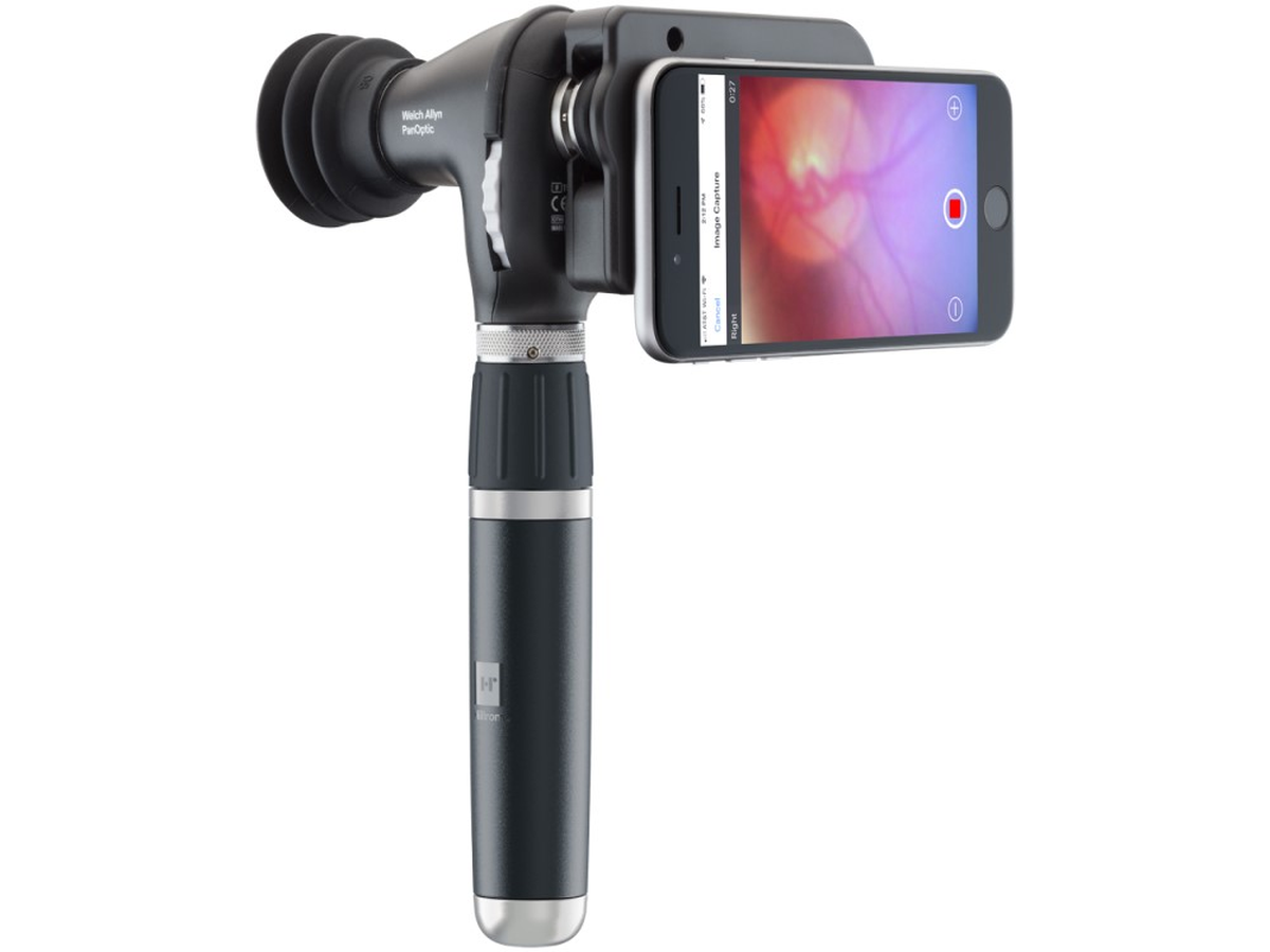
The PanOptic Plus can integrate with the iExaminer smartphone adapter system for fundus photography and digital documentation. This system uses precision optics to align a smartphone camera with the PanOptic's optical path, enabling capture of fundus images for patient records and telemedicine applications.
Common Integration Issues
Technicians may encounter several issues when supporting iExaminer systems:
- Alignment Problems: The smartphone camera lens must precisely align with the PanOptic optical axis. Misalignment causes vignetting or partial images. Verify the iExaminer adapter is properly seated on the PanOptic head and the smartphone is correctly positioned in the adapter.
- Image Quality Issues: Digital images may show poor quality despite acceptable direct viewing. This typically indicates smartphone camera settings issues (HDR mode, flash enabled, digital zoom) or inadequate ambient light control. Disable all automatic camera features and use the device in a dimly lit environment.
- Focus Discrepancies: The smartphone camera and clinician's eye may not achieve sharp focus simultaneously due to differences in refractive error. Optimize diopter setting for image capture rather than direct viewing when using iExaminer system.
Preventive Maintenance Schedule
After Each Use (Clinical Staff)
- Clean corneal viewing lens with lens tissue
- Wipe exterior surfaces with approved disinfectant (70% isopropyl alcohol or quaternary ammonium compound)
- Return to charging cradle or protective case
- Inspect for obvious damage or loose components
Monthly (Biomedical Engineering)
- Complete optical cleaning of all accessible surfaces
- Lamp brightness assessment using light meter
- Mechanical function test of all controls (diopter wheel, aperture selector)
- Handle battery and power supply verification
Quarterly
- Deep cleaning including disassembly of optical head
- Lamp replacement if brightness <80% of new lamp output
- Lubrication of mechanical assemblies
- Comprehensive functional testing using artificial eye model
Annual
- Complete optical alignment verification using optical bench
- Replacement of consumables (lamp, aperture filters if applicable)
- Structural integrity inspection for impact damage
- Documentation update including maintenance history and performance records
Technical Specifications
| Parameter | Specification |
|---|---|
| Field of View | 25 degrees (5x larger than standard ophthalmoscopes) |
| Optic Disc Visualization | Up to 95% in single view |
| Magnification | Approximately 5x at 25 cm working distance |
| Diopter Range | -25 to +40 diopters |
| Illumination System | 3.5V Halogen HPX, approximately 150-hour lamp life |
| Aperture Selections | Full spot, small spot, red-free filter, corneal lens, slit |
| Working Distance | Approximately 25 cm (10 inches) from patient |
| Power Requirements | 3.5V rechargeable handle or AA battery handle |
| Weight | Approximately 280g (without handle) |
| Operating Temperature | 50°F to 95°F (10°C to 35°C) |
Frequently Asked Questions
⚠ Safety and Handling
Optical Safety
- Never look directly into the illuminated PanOptic without first positioning against a patient's eye or artificial eye model
- Prolonged direct viewing of the light source may cause temporary vision impairment
- Ensure proper infection control between patients to prevent disease transmission
Maintenance Safety
- Always disconnect power source (remove from handle) before disassembly
- Use appropriate ESD protection when handling internal components
- Avoid touching optical surfaces with bare hands—skin oils will damage coatings
- Ensure proper reassembly to maintain structural integrity and optical alignment
Clinical Safety
- Verify proper calibration and image quality before returning to clinical service
- Document all maintenance and repairs in device service records
- Train clinical staff on proper technique and limitations of the device
Legal Disclaimer: This guide is intended for qualified biomedical technicians with appropriate optical instrument training. Always consult manufacturer service documentation. Improper repairs may compromise optical performance and patient safety.